Files and Items in the product knowledge graph
This is the second article in the series of articles about OpenBOM engineering frontend. The first article is here – OpenBOM Engineering Frontend for Complex Product Development
A computer-aided design (CAD) assembly and a product bill of materials answer different questions. For a complex product, the distinction also extends to electrical schematics, board designs, and software releases. OpenBOM connects these contributions while preserving their engineering meaning.
What is the difference between Design Folders, Design BOM and Engineering BOM
In OpenBOM’s managed-file model, a Design BOM (DBOM) describes the CAD files, an assembly references and links them to captured file versions. An Engineering BOM (EBOM) describes a product through engineering Items, Part Numbers, quantities, and properties. A Design Folder organizes the files. These structures remain distinct even when they describe the same design work.
| Structure | Main question | What it represents |
|---|---|---|
| Design Folder | Where is the design data stored? | Files, folder organization, and file versions |
| Design BOM | What does the assembly reference? | CAD file dependencies and their reference structure |
| Engineering BOM | Which Items define this product? | Engineering Items and their uses in a product |
With cloud CAD or a connected product data management (PDM) source, design objects and states can remain in that source. The integration brings supported engineering information and source links into OpenBOM. The semantic distinction between design and product remains useful across both paths.
The series begins with OpenBOM Engineering Frontend for Complex Product Development, which explains the configurable, multi-tenant foundation. This article examines the engineering ontology built on that architecture.
What is an engineering ontology
An engineering ontology is a semantic model that defines the kinds of information we manage, what each one means, and how they relate. It gives us a consistent vocabulary for distinguishing a CAD file from an engineering Item, or a component reference from its use in a product.
The design domain describes source artifacts and states: CAD geometry and assembly dependencies, electrical schematics, printed circuit board (PCB) projects, software references, and supporting documents. The engineering domain describes reusable Items, their properties, their use in product structures, and engineering revisions. Together, these domains explain how contributions from several tools support one engineering product definition.
Here, ontology means OpenBOM’s vocabulary and relationships for design and engineering information. It is not a claim that every CAD or PLM system uses the same terminology. The Design Projects and PDM service data model explains the underlying separation between managed design data and engineering product structure.
One conveyor example across engineering disciplines
Consider a conveyor designed in SOLIDWORKS discussed in the previous article. One assembly file contains a one-meter configuration and a two-meter configuration, sold as products CNV-1000 and CNV-2000. They use different frames and motors, with eight and sixteen rollers respectively. The conveyor also includes an electrical harness, a controller PCB, and firmware developed in other tools. These names, Part Numbers, and quantities are illustrative.
For the engineer, both products begin with the same assembly file. For purchasing and manufacturing, they have different Part Numbers and component requirements. A file name alone cannot express that difference.
The mechanical assembly is one contribution to the complete conveyor product. Its electrical harness, printed circuit board (PCB) assembly, and firmware also need engineering identities and source context. OpenBOM’s hardware and software product model supports discipline-specific schemas within connected product structures.
| Discipline | Engineering definition | Source context to preserve |
|---|---|---|
| Mechanical | Frame and roller Items with BOM usage quantities | CAD configuration and captured design state |
| Electrical | Harness Item HAR-100 and electrical components | Schematic state, tags, and source identifiers |
| Electronics and PCB | Controller assembly PCB-CTRL-100 and its component structure | PCB project state and component reference designators |
| Software | Firmware Item FW-CTRL used by the controller | Selected release or commit reference and repository location |
These additional identifiers are illustrative. A PCB reference designator describes a component’s position or usage in the board; it is different from the reusable component’s Part Number. A firmware release identifies a software state; it is different from the engineering Item identity that connects it to the product. Mapping keeps these meanings intact.
The managed-file DBOM described earlier is one source model. Electrical, PCB, and software tools have their own structures and state mechanisms. Their outputs can contribute to the product without being forced through a mechanical assembly tree.
Design Folders organize files and versions
A Design Folder represents the organization of files managed in OpenBOM. Engineers can organize parts, assemblies, purchased components, and drawings in folders that fit their work. Files have their own version histories as changes are uploaded and synchronized.
The folder hierarchy describes storage organization. The conveyor assembly might reference files from Parts, Assemblies, and Purchased folders. A roller stored once can be used by several assemblies. The assembly’s component relationships are captured separately in its Design BOM.
The folder layer also preserves the difference between a file and a particular state of that file. Roller.SLDPRT identifies the design file in this example; its version identifies the captured content associated with a particular update.
Design BOMs capture assembly dependencies
The Design BOM, or DBOM, describes the assembly reference structure. It records which part and subassembly files an assembly references and how those references form a hierarchy. In OpenBOM’s file-based model, Link to Design connects a referenced file to a particular version in its Design Folder.
For Conveyor.SLDASM, the DBOM includes the frame, rollers, fasteners, and motor files. It also includes Fixture.SLDPRT, an assembly aid that is referenced in CAD but excluded from the engineering BOM.
This model maintains one DBOM per assembly file, covering its references across configurations. Both motor files can therefore appear in the conveyor’s DBOM even though each product uses only one motor.
DBOM quantities count reference occurrences. In our example, the assembly contains sixteen roller occurrences, eight of which are suppressed in the shorter configuration. The DBOM can show sixteen while the shorter conveyor’s EBOM requires eight.
Drawings are stored as files and linked to the designs they document. They do not become component children in the assembly reference tree.
The captured scope matters. In this file-based workflow, references outside the mapped Design Folder are excluded from the DBOM. Teams need to account for that boundary when reviewing assembly dependencies.
Engineering BOMs define products through Items
The Engineering BOM, or EBOM, describes the product through engineering Items identified by Part Number. CAD integration supplies the initial structure and properties, which can then be extended in OpenBOM.
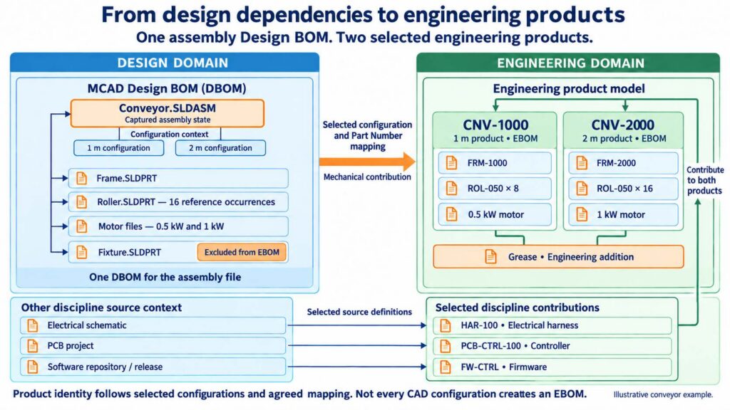
For our conveyor, the two configurations represent distinct engineering products. The same Frame.SLDPRT file represents Item FRM-1000 in the one-meter product and FRM-2000 in the two-meter product. Each product has its own EBOM with the appropriate components and quantities.
| Engineering definition | One-meter conveyor | Two-meter conveyor |
|---|---|---|
| Product Part Number | CNV-1000 | CNV-2000 |
| Frame Item | FRM-1000 | FRM-2000 |
| Roller Item ROL-050 quantity | 8 | 16 |
| Motor | 0.5 kW motor | 1 kW motor |
| Assembly fixture | Excluded | Excluded |
| Grease added in OpenBOM | Included | Included |
Configuration mapping determines which source configurations become engineering products. An assembly can produce several EBOMs when its configurations are assigned distinct product identities; every CAD configuration does not necessarily require a separate product.
Within the EBOM, OpenBOM also distinguishes the reusable Item definition from its usage in a product. The roller’s Part Number and engineering description belong to the Item. Its quantity belongs to the BOM usage: eight in one conveyor, sixteen in the other.
This reference–instance model allows the same engineering Item to participate in multiple product structures with different usage information.
Can one CAD file represent multiple engineering Items
Yes. One CAD file can represent multiple engineering Items when its configurations map to distinct Part Numbers. Conversely, several design representations can describe one Item. In OpenBOM, the mapping preserves the distinction between the source artifact and the product identity. The conveyor illustrates four useful relationships:
- One file can represent several Items. Frame.SLDPRT defines two frames through its configurations.
- Several design representations can describe one Item. A purchased sensor can appear in a mechanical CAD (MCAD) model and an electrical schematic while referring to one engineering Part Number through the configured mapping.
- An Item can exist without a separate CAD file. A virtual belt is stored inside the assembly, while grease is added directly to the EBOM in OpenBOM.
- A design file can exist without an EBOM Item. The fixture remains a design dependency even though it is excluded from the product definition.
These relationships explain why generating an EBOM involves engineering interpretation. CAD supplies design information; configuration, Part Number, inclusion, and usage rules determine the resulting product structure.
Treating every file as an Item would lose these distinctions. A configured frame would have an ambiguous engineering identity, duplicate bolt models could create duplicate purchasing identities, and non-modeled components would have no natural place in the product definition.
How are PCB revisions and software releases connected to the product
OpenBOM connects a board or software Item to the product and records the selected source state or reference. A PCB revision and a firmware release can advance independently. Engineering review establishes the combination accepted for the product; the captured product revision and its supporting evidence must preserve that selection.
A file version captures an update to an individual file. A design revision captures a selected state of the design reference structure. An Item or BOM revision captures an engineering definition through the applicable revision and change-management process.
An engineer can update the frame repeatedly, capture a meaningful assembly state, and revise the product definition when appropriate. These counters need not match. Uploading files or importing a CAD BOM does not by itself create an approved engineering revision.
Mechanical file versions, PCB revisions, and software releases can advance independently. The accepted product definition must identify the combination reviewed for use together. Historical traceability depends on the source states and relationships preserved for a revision. A working view of current design data answers a different question from a preserved baseline. The third article follows the events that create these states.
How does a product knowledge graph connect design and engineering
A product knowledge graph connects design sources, engineering Items, product usages, and supporting records through relationships. OpenBOM’s engineering ontology defines what those relationships mean. Together they provide engineering context: the source and state, configuration, Item identity, usage, documents, and lifecycle information needed to understand an object in a product.
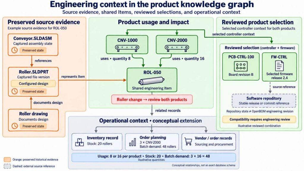
For roller Item ROL-050, that context can include its linked CAD representation and captured version, the assemblies referencing it, and the engineering products using it. The available evidence depends on the source information and links actually captured. Before changing the roller, an engineer can examine where it is used. When reviewing the two-meter conveyor, the engineer can examine the linked design information supporting its definition.
The relationships carry meaning. A folder contains a file. An assembly references another design file. A selected configuration can be mapped to an engineering Item. A BOM uses that Item with a quantity. A drawing documents a design. Keeping these meanings explicit makes the connections useful for engineering decisions.
Context also depends on origin. Grease is an engineering addition; the virtual belt comes from the containing assembly. Firmware can reference a selected repository state. The product graph connects these different kinds of evidence according to their meaning. Compatibility between a PCB revision and a firmware release requires engineering review and a recorded selection; a link alone does not establish it.
The Item connects engineering and operational context
The same Item identity can connect the engineering definition to inventory and ordering. These records have different meanings. An EBOM quantity describes how many rollers a product requires. Quantity on Hand describes stock recorded for the Item. An Order BOM calculates component demand for a planned batch. Three CNV-2000 conveyors require forty-eight rollers, before the planning process considers available stock and other adjustments.
Keeping these contexts explicit lets engineering and purchasing use related information without confusing product usage, stock, and batch demand. These connections support OpenBOM’s own operational workflows and provide a basis for mapping engineering information into enterprise systems.
xBOM connects disciplines and lifecycle perspectives
The xBOM model connects different bill-of-materials types as configurable product representations within the connected graph. There are two dimensions to keep clear. Discipline contributions describe the mechanical, electrical, electronic, and software content. Lifecycle perspectives describe how engineering, manufacturing, purchasing, and service use that content.
As discussed in Re-Thinking PLM with OpenBOM xBOM Workspace, these perspectives operate on a connected product model. They can have different relationships, usage properties, and responsibilities. Manufacturing can organize board installation and firmware loading while service identifies replaceable modules and supported software states. The necessary relationships and transformations are configured for the process. Single-level, multi-level, and flattened displays are presentation choices within a structure.
The same model can connect contributions from different companies. A board supplier maintains its own definitions and shares selected information under its permissions. The manufacturer manages how that contribution is used in the product and which state it accepts. The model records engineering context; company access and the agreed process preserve independent authority.
OpenBOM Engineering Frontend uses this ontology to connect multidisciplinary design information with product definitions. Engineers keep their specialized tools while the product model connects their work through Items, relationships, and reviewed states.
The next article, From CAD to Manufacturing: Engineering Release and ERP Integration, follows this model through design capture, engineering review, and revision. It then shows how the accepted definition can support OpenBOM inventory and ordering or a controlled handoff to enterprise product lifecycle management (PLM) and enterprise resource planning (ERP) systems.
Meantime REGISTER FOR FREE to check how OpenBOM can help you.
Best, Oleg
Join our newsletter to receive a weekly portion of news, articles, and tips about OpenBOM and our community.