Managing a bill of materials for a SolidWorks sheet metal design is very different from managing a standard mechanical part. A sheet metal part may start life as a flat body, pass through bending operations, and end up as a formed component that must still be manufactured from a flat pattern. This dual nature creates challenges when engineers try to generate accurate BOM data for purchasing, costing, and production.
While SOLIDWORKS provides powerful sheet metal tools, many teams struggle to turn design data into a clean, manufacturing-ready BOM. Properties like surface area, bend data, and flat pattern dimensions are often misunderstood or misused. This article explains how SolidWorks handles sheet metal BOM data, why errors happen, and how OpenBOM helps engineers manage sheet metal BOMs more reliably.
Understanding SolidWorks Sheet Metal Design Fundamentals
SolidWorks sheet metal design uses a dedicated workflow that is fundamentally different from modeling a solid block. Instead of sculpting geometry freely, engineers work within the Sheet Metal tab, which contains specialized tools designed to preserve manufacturability.
Most sheet metal parts begin with Base Flange/Tab, which creates the initial flat sheet from a sketch. From there, features such as Edge Flange and Sketched Bend define how the material is formed. SolidWorks automatically applies bend reliefs to prevent overlapping material, and the Flatten/Unfold command converts the formed model back into its flat, manufacturable state.
Key features like Gauge Tables control thickness and bend radius based on real manufacturing capabilities. Best practice dictates that the bend radius should be equal to or greater than the material thickness to prevent cracking or springback. Using the Sheet Metal toolbar from the start ensures that bend allowances, flat pattern length, and downstream BOM data remain accurate.
How SolidWorks Generates Sheet Metal BOM Data
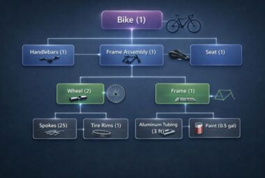
SolidWorks can generate a BOM at several levels, including part, assembly, and drawing. For sheet metal, the most important data often lives in Cut List Properties, not standard part properties. This is especially true when working with multibody sheet metal parts or weldments.
The BOM type you choose matters. In many cases, the Multi-Level BOM is recommended because it displays hierarchical relationships clearly while allowing sheet metal properties to appear correctly. However, simply inserting a BOM does not guarantee correct data. Many BOM columns rely on custom properties that must be filled or calculated manually.
This is where problems begin: SolidWorks can display sheet metal information in a BOM, but only if the correct properties exist and are mapped properly.
Why Surface Area and Flat Pattern Data Are Often Wrong in BOMs
A common mistake in sheet metal BOMs is relying on the Surface Area property found in Cut List Properties. This value represents the sum of all surfaces on the formed part, including bends, and does not accurately reflect the greatest flat pattern area required for material estimation and manufacturing.
To calculate meaningful flat pattern data, engineers should use the Bounding Box feature. SolidWorks automatically generates properties such as Bounding Box Area, Bounding Box Length, and Bounding Box Width, which represent the smallest rectangular area that contains the flat pattern.
Using Bounding Box Area and Bounding Box Area-Blank provides a far more reliable estimate of material usage. These properties are especially useful for nesting, costing, and procurement, where flat stock size matters more than formed geometry.
Using Bounding Box Properties in a SolidWorks Sheet Metal BOM
The Bounding Box Area can be shown in a Bill of Materials if it is exposed as a custom property. This requires accessing the Cut List Properties of the sheet metal part and creating a property that references the bounding box values.
Once created, these properties can be added as BOM columns in drawings. Engineers can also use equations within the BOM to calculate totals, apply minus signs where needed, or convert units. For repetitive workflows, this process can be automated using a macro built with the SolidWorks API, reducing manual steps and improving consistency.
This approach allows the BOM to reflect real manufacturing data rather than misleading geometric values.
Managing Flat Pattern Information in Drawings and BOMs
SolidWorks allows flat pattern information to be displayed in a drawing BOM, but there are important constraints. Flat pattern descriptions may need to be manually filled in the Cut List Properties by the engineer, and annotations must be attached directly to the Flat Pattern view to display correctly.
Users can create custom annotations mapped to specific sheet metal properties using predefined property syntax and saving as styles and templates. Saving BOM styles and drawing templates ensures consistency across projects, especially when working with multiple sheet metal components or assemblies. While effective, this can be laborious and require maintenance.
Exporting Flat Patterns for Manufacturing
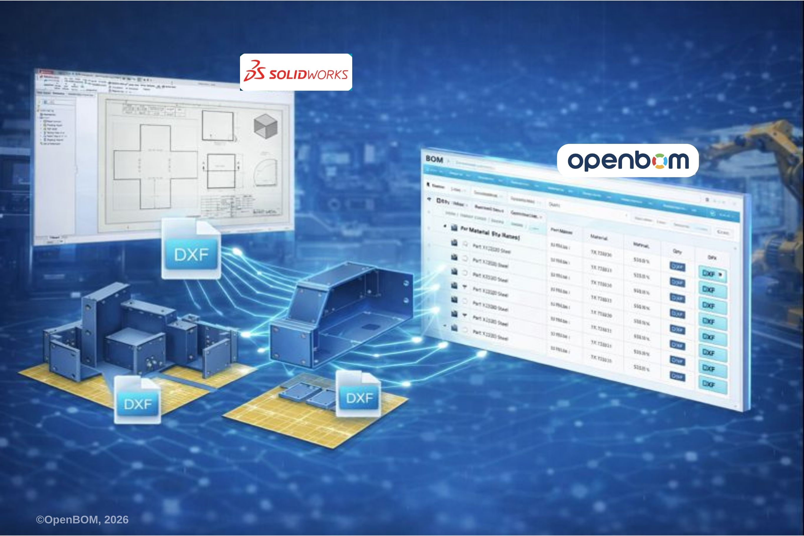
For fabrication, flat patterns are typically exported as DXF or DWG file types. Best practice is to ensure clear layer separation between cut lines and bend lines so CNC machines can interpret the data correctly. Incorrect exports can cause production errors even when the BOM itself is accurate. (See more here: New OpenBOM Feature for Solidworks Boosts Productivity through Automatic DXF Flat Pattern Creation)
How OpenBOM Helps You Manage SolidWorks Sheet Metal Design BOM
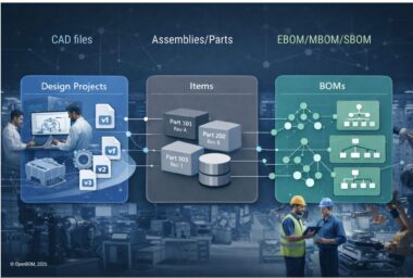
While SolidWorks can generate sheet metal BOM data, managing that data across revisions, assemblies, and teams is difficult. OpenBOM acts as a dedicated BOM management layer that integrates directly with SolidWorks.
OpenBOM extracts BOM data automatically, including the 1:1 DXF flat pattern (a huge win for manufacturing teams), Bounding Box Area, custom properties, material, length, and quantity. It supports multi-level BOMs, making it easier to manage sheet metal parts alongside weldments and other components. Changes in SolidWorks propagate automatically, reducing manual edits and Excel-based processes.
By separating design from BOM management, OpenBOM ensures that purchasing, manufacturing, and engineering all work from the same trusted data source.
Managing Multi-Level BOMs for Sheet Metal
Real products rarely consist of isolated sheet metal parts. They include weldments, gussets, brackets, and secondary components. Multi-level BOMs allow engineers to see each component’s role while preserving quantity rollups and length calculations.
The embedded video below demonstrates how individual cut list items, material descriptions, angled cuts, and total lengths are aggregated into a clean, multi-level BOM structure.
🎥 Embedded video: SolidWorks weldment and sheet metal BOM preview
Best Practices for Accurate Sheet Metal BOMs
When configurations are used to represent multiple sheet metal variants, following SolidWorks configuration best practices is critical to prevent duplicated parts, incorrect quantities, and BOM inconsistencies.
- Start designs using the Sheet Metal toolbar
- Use Gauge Tables aligned with manufacturing capabilities
- Avoid overlapping geometry near bend zones
- Use Forming Tools for louvers and ribs
- Prefer Bounding Box Area over surface area for costing
- Standardize custom properties early
- Avoid manual Excel edits
FAQ: SolidWorks Sheet Metal BOM Management
Can OpenBOM for Solidworks automatically create DXFs of all sheetmetal in my design?
Yes, OpenBOM for SolidWorks automatically creates flat pattern DXFs of every sheetmetal part in your design and links them to the item in the digital BOM, ready to send to the manufacturing shop floor or supplier to program the machines.
Can SolidWorks create a BOM?
Yes, SolidWorks can create BOMs in assemblies and drawings, but accuracy depends on correct properties and BOM configuration.
How to make a Bill of Materials in a SolidWorks drawing?
Insert a BOM from the drawing toolbar and select the appropriate BOM type, often an indented BOM for sheet metal.
What does BOM mean in SolidWorks?
A BOM is a structured list of components, quantities, and properties used for manufacturing and procurement.
How to organize BOM in SOLIDWORKS?
Use cut list properties, consistent templates, and indented BOM types to maintain clarity.
How to customize a BOM table in SOLIDWORKS?
Add or remove BOM columns, map custom properties, and save BOM styles for reuse.
How do you change the BOM description in SOLIDWORKS?
Edit the description property in the Cut List or part properties and rebuild the BOM.
How does OpenBOM make the SOLIDWORKS BOM creation process easier?
By capturing right information, attributes, files and attaching them to OpenBOM Digital BOM, engineers are getting a one-click BOM that contains the entire information (not only a spreadsheet), eliminating uploading files separately, and keeping track of all dependencies.
Conclusion
Accurate sheet metal BOMs require more than inserting a table into a drawing. They depend on correct design practices, meaningful properties like Bounding Box Area, and consistent data management, which requires generating files (eg. Sheet metal DXF flat patterns, and others). SolidWorks provides the geometry and tools, but OpenBOM ensures that sheet metal BOM data remains accurate, structured, and usable across the entire product lifecycle.
REGISTER FOR FREE and start using OpenBOM today!
Best, Oleg
Join our newsletter to receive a weekly portion of news, articles, and tips about OpenBOM and our community.